A3D Procgen Toolkit - Node Reference
Math & Numerical Methods
A3D_(A op B)^n
Description
Applies a selectable math operation to two values, then raises the result to a given exponent.
Inputs
- NameTypeDescription
- Operation
MenuType of operation to perform - A
FloatFirst operand - B
FloatSecond operand - Exponent
FloatPower the result is raised to
Outputs
- NameTypeDescription
- Value
FloatResult of the operation raised to the exponent
A3D_A^n op B^n
Description
Raises inputs A and B to a given exponent before combining them with a selectable math operation.
Inputs
- NameTypeDescription
- Operation
MenuType of operation to perform - A
FloatFirst operand, raised to the exponent - B
FloatSecond operand, raised to the exponent - Exponent
FloatPower A and B are raised to
Outputs
- NameTypeDescription
- Value
FloatResult of the operation
A3D_Angle Between Vectors
Description
Computes the angle in radians between two input vectors.
Inputs
- NameTypeDescription
- Vector A
VectorFirst vector - Vector B
VectorSecond vector
Outputs
- NameTypeDescription
- Radians
FloatAngle between the vectors in radians
A3D_Angle to Vector
Description
Converts a 2D angle (radians) into a unit direction vector.
Inputs
- NameTypeDescription
- Angle
FloatAngle in radians
Outputs
- NameTypeDescription
- Vector
VectorUnit direction vector for the angle
A3D_Axis Alignment
Description
Determines which world axis (X, Y, or Z) a given vector is most closely aligned to, within an epsilon tolerance, and outputs boolean results per axis.
Inputs
- NameTypeDescription
- Vector
VectorDirection Vector - Epsilon
FloatComparison threshold
Outputs
- NameTypeDescription
- X
BooleanAligned to X Axis - Y
BooleanAligned to Y Axis - Z
BooleanAligned to Z Axis
A3D_Axis Picker
Description
A menu-driven axis picker that outputs a unit vector for the selected X, Y, or Z axis, with an invert option.
Inputs
- NameTypeDescription
- Axis
MenuDirection to Return - Invert
BooleanFlip the direction of the returned axis
Outputs
- NameTypeDescription
- Vector
VectorDirection unit vector
A3D_Ballistic Arc
Description
Computes the position and velocity of a point along a ballistic (projectile) trajectory at a given time, from an initial position, initial velocity, and gravity vector.
Inputs
- NameTypeDescription
- Initial Position
VectorPosition at launch - Initial Velocity
VectorVelocity at launch - Gravity
VectorGravity acceleration vector - Time
FloatTime elapsed since launch
Outputs
- NameTypeDescription
- Position
VectorPosition at the given time - Velocity
VectorVelocity at the given time
A3D_Bell Curve
Description
Evaluates a Gaussian (normal distribution) bell curve for an input value, given a mean and standard deviation.
Inputs
- NameTypeDescription
- Value
FloatValue to evaluate the curve at - Mean
FloatCenter (peak) of the curve - Standard Deviation
FloatWidth of the curve
Outputs
- NameTypeDescription
- Value
FloatHeight of the curve at the input value
A3D_Bounce Reflect
Description
Reflects an incoming velocity off a plane defined by a normal, with restitution controlling bounce energy retention and friction damping the tangential component.
Inputs
- NameTypeDescription
- Incoming Velocity
VectorVelocity before the bounce - Plane Normal
VectorNormal of the surface being bounced off - Restitution
FloatFraction of energy kept after the bounce - Friction
FloatDamping applied to the tangential component
Outputs
- NameTypeDescription
- Reflected Velocity
VectorVelocity after the bounce
A3D_Clamp Vector
Description
Clamps each component of a vector independently between corresponding min and max vectors.
Inputs
- NameTypeDescription
- Vector
VectorVector to clamp - Min
VectorPer-component minimum - Max
VectorPer-component maximum
Outputs
- NameTypeDescription
- Vector
VectorClamped vector
A3D_Cotangent
Description
Computes the cotangent of an angle in radians.
Inputs
- NameTypeDescription
- Value
FloatAngle in radians
Outputs
- NameTypeDescription
- Value
FloatCotangent of the angle
A3D_Derivative
Description
Numerically differentiates a function closure at a point X using a finite-difference delta, returning the local slope and Y-intercept of the tangent line.
Inputs
- NameTypeDescription
- Function Closure
ClosureFunction to differentiate - X
FloatPoint to evaluate the slope at - Delta
FloatStep size for the finite difference
Outputs
- NameTypeDescription
- Slope
FloatSlope of the tangent line at X - Y Intercept
FloatY intercept of the tangent line
A3D_Distance From Axis
Description
Computes the perpendicular distance from a position to an infinite axis defined by an origin and direction.
Inputs
- NameTypeDescription
- Position
VectorPosition to measure from - Origin
VectorPoint on the axis - Axis
VectorDirection of the axis
Outputs
- NameTypeDescription
- Distance
FloatPerpendicular distance from the position to the axis
A3D_Distance From Plane
Description
Computes the signed distance from a position to a plane defined by an origin and two in-plane axis vectors.
Inputs
- NameTypeDescription
- Position
VectorPosition to measure from - Origin
VectorOrigin of the plane - U Axis
VectorFirst in-plane axis - V Axis
VectorSecond in-plane axis
Outputs
- NameTypeDescription
- Distance
FloatSigned distance from the position to the plane
A3D_Golden Ratio
Description
Outputs the constant φ (the golden ratio, ≈1.618) for use in proportion-driven procedural setups.
Inputs
This node has no inputs.
Outputs
- NameTypeDescription
- Phi
FloatThe golden ratio, approximately 1.618
A3D_Integer Clamp
Description
Clamps an integer value between a minimum and maximum.
Inputs
- NameTypeDescription
- Value
IntegerValue to clamp - Min
IntegerMinimum allowed value - Max
IntegerMaximum allowed value
Outputs
- NameTypeDescription
- Value
IntegerClamped value
A3D_Midpoint Range to Min Max
Description
Converts a midpoint-and-range pair into explicit min/max bounds.
Inputs
- NameTypeDescription
- Midpoint
FloatCenter of the range - Range
FloatTotal width of the range
Outputs
- NameTypeDescription
- Min
FloatLower bound of the range - Max
FloatUpper bound of the range
A3D_Multivariate Newton Solver
Description
Solves a system of equations for a root using multivariate Newton's method, iterating from an initial guess with a configurable step size and function closure.
Inputs
- NameTypeDescription
- Function Closure
ClosureFunction to find the root of - Iterations
IntegerNumber of Newton iterations - Initial Guess
VectorStarting point for the search - Step Size
FloatStep size used for the numerical derivative
Outputs
- NameTypeDescription
- Root
VectorRoot found by the solver
A3D_Plane Normal
Description
Computes the normal vector of the plane defined by three points.
Inputs
- NameTypeDescription
- Point A
VectorFirst point on the plane - Point B
VectorSecond point on the plane - Point C
VectorThird point on the plane
Outputs
- NameTypeDescription
- Vector
VectorNormal vector of the plane
A3D_Point Slope Line
Description
Constructs a line segment of a given length from a point-slope definition (X, Y, slope), returning its start and end points.
Inputs
- NameTypeDescription
- X
FloatX coordinate of the point - Y
FloatY coordinate of the point - Slope
FloatSlope of the line - Length
FloatLength of the line segment
Outputs
- NameTypeDescription
- Start Point
VectorStart of the line segment - End Point
VectorEnd of the line segment
A3D_Univariate Newton Solver
Description
Solves for a root of a single-variable function closure using Newton's method, iterating from an initial guess with a configurable epsilon and step size, and reporting convergence.
Inputs
- NameTypeDescription
- Function Closure
ClosureFunction to find the root of - Iterations
IntegerNumber of Newton iterations - Initial Guess
FloatStarting value for the search - Epsilon
FloatTolerance used to test convergence - Step Size
FloatScale of each Newton step
Outputs
- NameTypeDescription
- Root
FloatRoot found by the solver - Converged
BooleanTrue if the solver converged
A3D_Vector to Angle
Description
Converts a 2D vector into its angle in radians.
Inputs
- NameTypeDescription
- Vector
Vector2D vector to convert
Outputs
- NameTypeDescription
- Radians
FloatAngle of the vector in radians
A3D_Wiggle
Description
Applies a physics-driven jiggle to a mesh using the motion of the object.
Inputs
- NameTypeDescription
- Geometry
GeometryThe mesh to apply the wiggle to - Influence
FloatPer-point strength of the wobble - Damping
FloatHow quickly the oscillation dies out - Frequency
FloatHow fast the mesh oscillates, in Hz - Gravity
VectorConstant acceleration in world space
Outputs
- NameTypeDescription
- Geometry
GeometryThe input geometry with the simulated wobble applied to its point positions.
Geometry Generation & Distribution
A3D_Dodecahedron
Description
Generates a regular dodecahedron mesh of a given radius, built from a convex hull of instanced pentagonal faces.
Inputs
- NameTypeDescription
- Radius
FloatRadius of the dodecahedron
Outputs
- NameTypeDescription
- Mesh
GeometryGenerated dodecahedron mesh
A3D_Fermat Spiral
Description
Generates a set of points arranged in a Fermat (golden-angle) spiral, controlled by point count and a scaling factor. Commonly used for even radial packing.
Inputs
- NameTypeDescription
- Count
IntegerThe number of points to create - Scaling Factor
FloatScales the spread of the spiral
Outputs
- NameTypeDescription
- Points
GeometryGenerated spiral points
A3D_Helix
Description
Displaces curve points into a helical pattern around the curve's path, driven by frequency, amplitude, and phase.
Inputs
- NameTypeDescription
- Curves
GeometryCurves to displace - Source
MenuSource used to orient the helix - Frequency
FloatTightness of the spiral - Amplitude
FloatRadius of the spiral - Phase
FloatOffset of the spiral
Outputs
- NameTypeDescription
- Curves
GeometryCurves displaced into a helix
A3D_Noodle
Description
Generates a tube ('noodle') mesh along a curve, with adjustable scale and profile/cap resolution.
Inputs
- NameTypeDescription
- Curve
GeometryCurve to generate the tube along - Scale
FloatRadius of the tube - Profile Resolution
IntegerNumber of points around the tube profile - Cap Resolution
IntegerNumber of segments in each end cap
Outputs
- NameTypeDescription
- Mesh
GeometryGenerated tube mesh
A3D_Patch Mesh
Description
Fills or patches holes in a mesh's topology.
Inputs
- NameTypeDescription
- Mesh
GeometryMesh to patch
Outputs
- NameTypeDescription
- Mesh
GeometryMesh with holes filled
A3D_Plexus
Description
Builds a connective 'plexus' mesh linking nearby points based on a connectivity parameter, commonly used for network/energy-field visuals.
Inputs
- NameTypeDescription
- Points
GeometryPoints to connect - Connectivity
IntegerMaximum number of connections per point
Outputs
- NameTypeDescription
- Mesh
GeometryGenerated network of connections
A3D_Quad Sphere
Description
Generates a quad-topology sphere (cube-projected) of a given radius and subdivision level, with a UV map output.
Inputs
- NameTypeDescription
- Radius
FloatRadius of the sphere - Subdivisions
IntegerNumber of subdivisions per cube face
Outputs
- NameTypeDescription
- Mesh
GeometryGenerated sphere mesh - UV Map
VectorUV coordinates of the sphere
A3D_Random Point In Shell
Description
Generates a seeded random point within a spherical shell between a minimum and maximum radius.
Inputs
- NameTypeDescription
- Min Radius
FloatRadius of inner boundary - Max Radius
FloatRadius of outer boundary - ID
IntegerID used to vary the random value per element - Seed
IntegerRandom Seed
Outputs
- NameTypeDescription
- Position
VectorRandom position within the shell
A3D_Random XY+Z
Description
Generates a seeded random vector with independently ranged XY (planar) and Z (vertical) components.
Inputs
- NameTypeDescription
- XY Min
FloatMinimum of the X and Y components - XY Max
FloatMaximum of the X and Y components - Z Min
FloatMinimum of the Z component - Z Max
FloatMaximum of the Z component - ID
IntegerID used to vary the random value per element - Seed
IntegerRandom seed
Outputs
- NameTypeDescription
- Vector
VectorRandom vector
A3D_Scatter Points
Description
Scatters points across a mesh surface using a selectable distribution mode, minimum spacing, and density falloff, returning per-point normal and rotation. When 'Use Rest Position' is True and the 'rest_position' attribute exists on the Geometry, the point positions are transferred from the un-deformed mesh to avoid popping.
Inputs
- NameTypeDescription
- Mesh
GeometryMesh to scatter points on - Mode
MenuChange distribution mode - Selection
BooleanFaces to scatter points on - Distance Min
FloatMinimum spacing between points - Density
FloatNumber of points per unit area - Density Factor
FloatFactor to scale the density by - Seed
IntegerRandom seed - Radius
FloatRadius stored on each point - Use Rest Position
BooleanRequires enabling 'Rest Position' in the Shape Keys panel
Outputs
- NameTypeDescription
- Points
GeometryScattered points - Normal
VectorSurface normal at each point - Rotation
RotationRotation aligned to the surface at each point
A3D_Tetrahedron
Description
Generates a regular tetrahedron mesh of a given radius.
Inputs
- NameTypeDescription
- Radius
FloatRadius of the tetrahedron
Outputs
- NameTypeDescription
- Mesh
GeometryGenerated tetrahedron mesh
A3D_Tetrahedron Volume
Description
Computes the signed volume of a tetrahedron defined by four vertices.
Inputs
- NameTypeDescription
- Vertex A
VectorFirst vertex of the tetrahedron - Vertex B
VectorSecond vertex of the tetrahedron - Vertex C
VectorThird vertex of the tetrahedron - Vertex D
VectorFourth vertex of the tetrahedron
Outputs
- NameTypeDescription
- Volume
FloatSigned volume of the tetrahedron
Mesh Editing & Construction
A3D_2D Line Cut
Description
Cuts a body mesh against a tool mesh's edges along a shared plane, returning the resulting mesh along with intersection status and position for each intersected element.
Inputs
- NameTypeDescription
- Body Mesh
GeometryGeometry to split - Tool Mesh
GeometryGeometry that will perform the cut - Selection
BooleanWhich edges in body geometry to cut - Cut Body
BooleanInsert new edge (cut) - Tool Index
IntegerIndex of edge in tool body to be used
Outputs
- NameTypeDescription
- Mesh
GeometryBody mesh with the cut applied - Intersected
BooleanTrue where the tool edge intersects the body - Position
VectorPosition of the intersection
A3D_2D Shape Cut
Description
Cuts a body mesh using an arbitrary 2D tool mesh as the cutting shape, returning the cut mesh, intersection status, and intersection positions.
Inputs
- NameTypeDescription
- Cut Body
BooleanInsert vertex (cut) geometry - Body Mesh
GeometryGeometry to be cut - Body Selection
BooleanLimit affected edges - Tool Mesh
GeometryCutting geometry
Outputs
- NameTypeDescription
- Mesh
GeometryBody mesh with the cut applied - Intersected
BooleanTrue where the tool mesh intersects the body - Intersection Position
VectorPosition of the intersection
A3D_Cell Fracture
Description
Fractures input geometry into a set of instanced cell pieces using Voronoi-style cell partitioning, with controls for fracture scale/detail/gap, remeshing, and edge-wear seeding.
Inputs
- NameTypeDescription
- Geometry
GeometryGeometry to fracture - Fracture Scale
FloatScale of Voronoi noise - Fracture Detail
FloatThe scale of a Voronoi layer relative to that of the previous layer - Fracture Gap
FloatSpacing between cells - Seed
IntegerRandom seed for the fracture pattern - Remesh Mode
MenuHow the geometry is remeshed before fracturing - Remesh Voxel Size
FloatSize of the voxels used when remeshing - Remesh Accuracy
IntegerAccuracy of the remesh - Edge Wear Seed
IntegerRandom seed for the edge wear pattern
Outputs
- NameTypeDescription
- Instances
GeometryFractured pieces as instances
A3D_Delaunay Triangulation
Description
Builds a Delaunay triangulation over the input geometry's points, with controls for minimum spacing, density falloff, boundary preservation, and inset.
Inputs
- NameTypeDescription
- Geometry
GeometryPoints to triangulate - Distance Min
FloatMinimum spacing between points - Density Max
FloatMaximum point density - Density Factor
FloatHow quickly density falls off - Seed
IntegerRandom seed - Keep Boundaries
BooleanPreserve the boundary of the input - Inset
FloatDistance to inset from the boundary
Outputs
- NameTypeDescription
- Geometry
GeometryTriangulated geometry
A3D_Edge Array
Description
Distributes instanced or inset geometry along selected edges at a controllable spacing/count, with per-instance scale, alignment, rotation, and randomized selection.
Inputs
- NameTypeDescription
- Mesh
GeometryGeometry whose elements are iterated over - Selection
BooleanSelection on the iteration domain - Inset
FloatInset applied to the generated geometry - Radius
FloatThe radius of the cylinder - Depth
FloatThe height of the cylinder - Vertices
IntegerThe number of vertices on the top and bottom circles - Length
FloatLength of each array element along the edge - Probability
FloatChance that each element is generated - Seed
IntegerRandom seed for the selection - Instance
GeometryGeometry that is instanced on the points - Pick Instance
BooleanChoose instances from the "Instance" input at each point instead of instancing the entire geometry - Scale
VectorScale of the instances - Align
BooleanAlign instances to the edge direction - Rotation
RotationRotation applied to each instance
Outputs
- NameTypeDescription
- Mesh
GeometryResult of joining generated geometries from each iteration
A3D_Expand Selection
Description
Grows or shrinks a boolean selection outward across a chosen domain by a number of steps, with probabilistic falloff and seeded randomness.
Inputs
- NameTypeDescription
- Selection
BooleanSelection to expand - Steps
IntegerNumber of steps to grow the selection - Domain
MenuDomain to expand across - Mode
MenuWhether the selection grows or shrinks - Probability
FloatChance that each neighbor is included per step - Seed
IntegerRandom seed
Outputs
- NameTypeDescription
- Result
BooleanExpanded selection
A3D_Inset Faces
Description
Face inset operation supporting individual or grouped insets, independent thickness/depth control, and even-distance/even-depth modes, returning the inset mesh split into inner and outer face groups.
Inputs
- NameTypeDescription
- Mesh
GeometryMesh to inset faces on - Selection
BooleanFaces to inset - Individual
BooleanInset each face separately - Thickness
FloatAmount to inset by - Depth
FloatOffset of the inset faces along their normal - Even Distance
BooleanKeep the inset distance even around corners - Even Depth
BooleanKeep the depth even across angled faces
Outputs
- NameTypeDescription
- Mesh
GeometryMesh with the faces inset - Inner
BooleanFaces created by the inset - Outer
BooleanFaces surrounding the inset faces
A3D_Iterate Over Edges
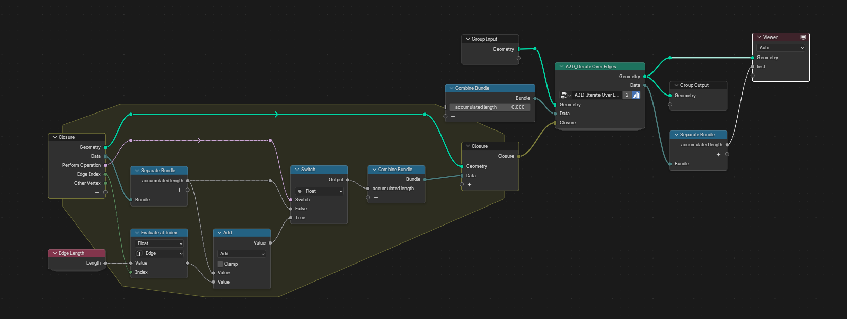
Description
Runs a closure once for every edge of the input geometry, carrying a bundle of variables from one edge to the next, and returns the processed geometry along with the final bundle.
Inputs
- NameTypeDescription
- Geometry
GeometryGeometry to process. Must contain edges. - Data
BundleBundle of variables that persist between edge iterations. - Closure
ClosureClosure to execute
Outputs
- NameTypeDescription
- Geometry
GeometryGeometry to process. Must contain edges. - Data
BundleBundle of variables that persist between edge iterations.
A3D_Merge by Distance
Description
Merges mesh elements within a given distance of each other, with options to limit merging to islands and to merge by group ID.
Inputs
- NameTypeDescription
- Mesh
GeometryPoint cloud or mesh to merge points of - Limit Islands
BooleanOnly merge elements within the same island - Group ID
IntegerOnly merge elements with the same group ID - Position
VectorPosition used to measure distances - Distance
FloatMaximum distance between elements to merge
Outputs
- NameTypeDescription
- Mesh
GeometryMesh with nearby elements merged
A3D_Mesh to Lattice
Description
Converts a mesh into a lattice-cell structure using a selectable cell type and object, with a configurable cell size and interior band width.
Inputs
- NameTypeDescription
- Mesh
GeometryMesh to convert - Cell Type
MenuType of cell to use for each lattice element - Cell Object
ObjectObject used as the lattice cell, must be exactly 1m³ - Cell Size
FloatSize of each lattice cell - Interior Band Width
FloatWidth of the gradient inside of the mesh
Outputs
- NameTypeDescription
- Mesh
GeometryLattice generated from the mesh
A3D_Mirror
Description
Mirrors a mesh across chosen X/Y/Z axes, either about the origin or about a separate mirror object.
Inputs
- NameTypeDescription
- Mesh
GeometryMesh to mirror - X
BooleanMirror across the X axis - Y
BooleanMirror across the Y axis - Z
BooleanMirror across the Z axis - Use Object
BooleanMirror about an object instead of the origin - Mirror Object
ObjectObject to mirror about
Outputs
- NameTypeDescription
- Mesh
GeometryMirrored mesh
A3D_Poke Faces
Description
Pokes (fan-triangulates from a center point) all faces in the input geometry.
Inputs
- NameTypeDescription
- Geometry
GeometryGeometry to poke faces on
Outputs
- NameTypeDescription
- Geometry
GeometryGeometry with faces poked
A3D_Poke Triangle
Description
Pokes a single face at a given position, splitting it into a triangle fan from that point.
Inputs
- NameTypeDescription
- Mesh
GeometryMesh containing the face to poke - Position
VectorLocation of central vertex
Outputs
- NameTypeDescription
- Mesh
GeometryMesh with the face poked
A3D_Random Triangulate
Description
Randomly triangulates a subset of the mesh's faces based on a seeded probability.
Inputs
- NameTypeDescription
- Mesh
GeometryMesh to triangulate - Probability
FloatChance that each face is triangulated - Seed
IntegerRandom seed
Outputs
- NameTypeDescription
- Mesh
GeometryMesh with some faces triangulated
A3D_Split Quad
Description
Splits a quad face into triangles or sub-quads along a chosen direction, by a blend factor.
Inputs
- NameTypeDescription
- Mesh
GeometryMesh containing the quads to split - Factor
FloatHow far along to split the face. 0.5 is the middle of the face - Direction
MenuRelative direction to split the face
Outputs
- NameTypeDescription
- Mesh
GeometryMesh with the quads split
A3D_UV Unwrap
Description
Unwraps a mesh's selected faces along seam edges using a selectable method, with margin, hole-filling, iteration, and no-flip controls.
Inputs
- NameTypeDescription
- Geometry
GeometryGeometry to unwrap - Selection
BooleanFaces to participate in the unwrap operation - Seam
BooleanEdges to mark where the mesh is "cut" for the purposes of unwrapping - Margin
FloatSpace between islands - Fill Holes
BooleanVirtually fill holes in mesh before unwrapping, to better avoid overlaps and preserve symmetry - Method
MenuUnwrapping algorithm - Iterations
IntegerNumber of iterations to run the SLIM solver for - No Flip
BooleanPrevents flipping UVs
Outputs
- NameTypeDescription
- Geometry
GeometryGeometry with the unwrapped UVs - UV
VectorUV coordinates between 0 and 1 for each face corner in the selected faces
Geometry Queries & Topology
A3D_Boolean Grid Check
Description
Tests a boolean value against a rectangular sub-region (width/height) of a resolution-addressed grid at a given index.
Inputs
- NameTypeDescription
- Index
IntegerIndex of the grid cell the sub-region is positioned at - Width
IntegerWidth of the sub-region in grid cells - Height
IntegerHeight of the sub-region in grid cells - Boolean
BooleanBoolean value to test - Resolution
IntegerResolution of the grid
Outputs
- NameTypeDescription
- Boolean
BooleanResult of the test over the sub-region
A3D_Circumcircle Test
Description
Determines whether a test point lies inside, on, or outside the circumcircle defined by three points.
Inputs
- NameTypeDescription
- Test Against
MenuField method for circle origins - Position
VectorPoint to test - Point A
VectorFirst triangle point - Point B
VectorSecond triangle point - Point C
VectorThird triangle point
Outputs
- NameTypeDescription
- Determinant
FloatSign shows whether the point is inside, on, or outside the circumcircle
A3D_Distance to Boundary
Description
Computes each element's distance to the nearest open/mesh boundary edge.
Inputs
- NameTypeDescription
- Geometry
GeometryGeometry to measure boundary distance on
Outputs
- NameTypeDescription
- Distance
FloatNumber of topology steps to the nearest edge
A3D_Edge Info
Description
Reports whether an edge is horizontal or vertical, its direction vector, and its length, for a given edge index.
Inputs
- NameTypeDescription
- Edge Index
IntegerIndex of the edge to read
Outputs
- NameTypeDescription
- Horizontal
BooleanTrue if the edge is horizontal - Vertical
BooleanTrue if the edge is vertical - Direction
VectorDirection vector of the edge - Length
FloatLength of the edge
A3D_Extended Vertex Neighbors
Description
Returns a sortable pair of neighboring vertex indices around a given vertex, along with the total connected vertex and face counts.
Inputs
- NameTypeDescription
- Vertex Index
IntegerThe vertex to retrieve data from. Defaults to the vertex from the context - Sort Index
IntegerWhich of the sorted edges to output
Outputs
- NameTypeDescription
- Vertex Index 1
IntegerIndex of the first sorted neighboring vertex - Vertex Index 2
IntegerIndex of the second sorted neighboring vertex - Vertex Count
IntegerThe number of vertices connected to this vertex with an edge, equal to the number of connected edges - Face Count
IntegerNumber of faces that contain the vertex
A3D_Face Corner Info
Description
Returns the position and corner index of a specific corner of a given face, offset from a weighted reference corner.
Inputs
- NameTypeDescription
- Face Index
IntegerThe face to retrieve data from. Defaults to the face from the context - Weights
FloatValues used to sort the face's corners. Uses indices by default - Offset
IntegerThe number of corners to move around the face before finding the result, circling around the start of the face if necessary
Outputs
- NameTypeDescription
- Position
VectorPosition of the resulting corner - Corner Index
IntegerA corner of the face, chosen by the sort index
A3D_Face Winding Direction
Description
Returns the signed winding direction (+1/-1) of the current face, useful for detecting flipped normals or inconsistent topology.
Inputs
This node has no inputs.
Outputs
- NameTypeDescription
- Sign
FloatWinding direction of the face, +1 or -1
A3D_Inside BBox
Description
Tests whether a position lies inside the bounding box of the input geometry.
Inputs
- NameTypeDescription
- Geometry
GeometryGeometry whose bounding box is tested - Position
VectorPosition to test
Outputs
- NameTypeDescription
- Inside
BooleanTrue if the position is inside the bounding box
A3D_Inside Frustum
Description
Tests whether a position lies inside a camera's view frustum, with configurable padding.
Inputs
- NameTypeDescription
- Source
MenuWhere the camera comes from - Camera
ObjectCamera object whose frustum is tested - Position
VectorPosition to sample (Default Position) - Horizontal Padding
FloatAmount to extend the frustum horizontally, along the camera's X axis - Vertical Padding
FloatAmount to extend the frustum vertically, along the camera's Y axis
Outputs
- NameTypeDescription
- In Frustum
BooleanReturns true if the position is inside the frustum
A3D_Inside Frustum (Legacy)
Description
An earlier frustum-containment test driven by explicit render resolution, padding, and camera FOV rather than direct camera data.
Inputs
- NameTypeDescription
- Use Active Camera
BooleanUse the active scene camera - Culling Camera
ObjectCamera object to test against - Horizontal Resolution
IntegerHorizontal render resolution - Vertical Resolution
IntegerVertical render resolution - Horizontal Padding
FloatAmount to extend the frustum horizontally - Vertical Padding
FloatAmount to extend the frustum vertically - Camera FOV
FloatField of view of the camera - Position
VectorPosition to test
Outputs
- NameTypeDescription
- Inside Frustum
BooleanTrue if the position is inside the frustum
A3D_Inside Prism
Description
Tests whether a position lies inside a prism volume defined by four reference points.
Inputs
- NameTypeDescription
- Position
VectorPosition to test - A
VectorFirst reference point of the prism - B
VectorSecond reference point of the prism - C
VectorThird reference point of the prism - D
VectorFourth reference point of the prism
Outputs
- NameTypeDescription
- Boolean
BooleanTrue if the position is inside the prism
A3D_Inside Quad Face
Description
Tests whether a position lies inside the bounds of a specific quad face.
Inputs
- NameTypeDescription
- Position
VectorPosition to test - Face Index
IntegerIndex of the quad face
Outputs
- NameTypeDescription
- Inside
BooleanTrue if the position is inside the face
A3D_Inside Rectangle
Description
Tests whether a position lies inside a rectangle defined by three of its corner vertices.
Inputs
- NameTypeDescription
- Position
VectorPosition to test - Vertex A
VectorFirst corner of the rectangle - Vertex B
VectorSecond corner of the rectangle - Vertex C
VectorThird corner of the rectangle
Outputs
- NameTypeDescription
- Boolean
BooleanTrue if the position is inside the rectangle
A3D_Largest Island
Description
Returns a boolean selection marking the largest connected mesh island.
Inputs
This node has no inputs.
Outputs
- NameTypeDescription
- Boolean
BooleanIs the largest mesh island
A3D_Line Intersect
Description
Tests whether two line segments (each defined by two endpoints) intersect.
Inputs
- NameTypeDescription
- Edge A Position 1
VectorFirst endpoint of edge A - Edge A Position 2
VectorSecond endpoint of edge A - Edge B Position 1
VectorFirst endpoint of edge B - Edge B Position 2
VectorSecond endpoint of edge B
Outputs
- NameTypeDescription
- Intersect
BooleanTrue if the two segments intersect
A3D_Line Intersect Point
Description
Computes the intersection point of two line segments (each defined by two endpoints), assuming they intersect.
Inputs
- NameTypeDescription
- Edge A Position 1
VectorFirst endpoint of edge A - Edge A Position 2
VectorSecond endpoint of edge A - Edge B Position 1
VectorFirst endpoint of edge B - Edge B Position 2
VectorSecond endpoint of edge B
Outputs
- NameTypeDescription
- Intersection Point
VectorPoint where the two segments intersect
A3D_Line-Line Intersection
Description
Combines intersection testing and position calculation for two line segments into a single node, returning both whether they intersect and where.
Inputs
- NameTypeDescription
- Edge A Position 1
VectorFirst endpoint of edge A - Edge A Position 2
VectorSecond endpoint of edge A - Edge B Position 1
VectorFirst endpoint of edge B - Edge B Position 2
VectorSecond endpoint of edge B
Outputs
- NameTypeDescription
- Intersects
BooleanTrue if the two segments intersect - Intersection Position
VectorPoint where the two segments intersect
A3D_Mesh Boundary
Description
Identifies the boundary of a mesh.
Inputs
This node has no inputs.
Outputs
- NameTypeDescription
- Boundary
BooleanReturns True or False if point is boundary
A3D_N Nearest Neighbors
Description
Finds the N nearest neighboring points to each input point. Writes each points index and position as 'a3d_neighbor_*'
Inputs
- NameTypeDescription
- Points
GeometryPoints to find neighbors for - Neighbors
IntegerNumber of nearest neighbors to find
Outputs
- NameTypeDescription
- Points
GeometryPoints with neighbor connections
A3D_Nearest Point Info
Description
Returns the index, radius, distance, direction, and offset of the nearest point (optionally within a group ID) to a given position.
Inputs
- NameTypeDescription
- Position
VectorPosition to sample from - Group ID
IntegerSplits the geometry into groups which can be sampled individually
Outputs
- NameTypeDescription
- Index
IntegerIndex of Nearest - Radius
Float'radius' attribute of Nearest - Distance
FloatDistance to Nearest - Direction
VectorNormalized direction towards Nearest - Offset
VectorOffset between current and Nearest
A3D_Neighbors of Vertex
Description
Returns a weighted, sortable list of a vertex's connected neighbor vertices and their total count.
Inputs
- NameTypeDescription
- Vertex Index
IntegerThe vertex to retrieve data from. Defaults to the vertex from the context - Weights
FloatValues used to sort the edges connected to the vertex. Uses indices by default - Sort Index
IntegerWhich of the sorted edges to output. Negative indexing is supported
Outputs
- NameTypeDescription
- Other Vertex
IntegerIndex of the selected neighboring vertex - Total
IntegerNumber of vertices connected to this vertex
A3D_Octree
Description
Builds an octree spatial subdivision of a point cloud between a min and max bound, iterating to the target depth.
Inputs
- NameTypeDescription
- Points
GeometryPoints to subdivide - Iterations
IntegerNumber of subdivision levels - Min
VectorMinimum corner of the bounds - Max
VectorMaximum corner of the bounds
Outputs
- NameTypeDescription
- Geometry
GeometryGenerated octree geometry
A3D_Opposite Corner of Triangle Adjacent to Edge
Description
Returns the vertex opposite an edge in a triangle attached to that edge, with weights and a sort index to choose between the attached corners.
Inputs
- NameTypeDescription
- Edge Index
IntegerThe edge to retrieve data from. Defaults to the edge from the context - Weights
FloatValues that sort the corners attached to the edge - Sort Index
IntegerWhich of the sorted corners to output. Negative indexing is supported
Outputs
- NameTypeDescription
- Vertex Index
IntegerThe vertex the corner is attached to
A3D_Quad Corners
Description
Returns the four corner positions (A–D) of a quad face at a given offset.
Inputs
- NameTypeDescription
- Face Index
IntegerThe face to retrieve data from. Defaults to the face from the context - Offset
IntegerNumber of corners to rotate the corner order by
Outputs
- NameTypeDescription
- Corner A
VectorPosition of the first corner - Corner B
VectorPosition of the second corner - Corner C
VectorPosition of the third corner - Corner D
VectorPosition of the fourth corner
A3D_Volume of Mesh
Description
Computes the enclosed volume of a mesh.
Inputs
- NameTypeDescription
- Mesh
GeometryMesh to measure
Outputs
- NameTypeDescription
- Volume
FloatVolume enclosed by the mesh
Curves & Surface Operations
A3D_Catenary Curve
Description
Relaxes a curve's selected control points into a catenary (hanging-chain) shape based on a stiffness parameter. Useful for cables, ropes, and chains.
Inputs
- NameTypeDescription
- Curve
GeometryCurve to relax into a catenary shape - Selection
BooleanControl points to affect - Stiffness
FloatHow rigid the hanging shape is
Outputs
- NameTypeDescription
- Curve
GeometryCurve with a catenary shape
A3D_Conform To Surface
Description
Snaps or projects a mesh's selected vertices onto a target surface mesh within a snapping distance, with an additional surface offset.
Inputs
- NameTypeDescription
- Mesh
GeometryMesh to snap - Selection
BooleanVertices to snap - Surface Mesh
GeometrySurface to snap to - Snapping Distance
FloatMaximum distance to search for the surface - Surface Offset
FloatOffset from the surface after snapping
Outputs
- NameTypeDescription
- Mesh
GeometryMesh with vertices snapped to the surface
A3D_Deform To UV Surface
Description
Deforms a mesh to conform to a target surface using a UV-space transfer map, with an optional debug output for visualizing the mapping. Input Mesh be placed within a +1 unit bounding box on the XY plane.
Inputs
- NameTypeDescription
- Mesh
GeometrySurface to deform - Transfer Surface
ObjectSurface to transfer to - Transfer Map
StringName of the UV transfer map to use - Debug
BooleanShow UV Space Geometry - Height
FloatHeight of instance outward from surface
Outputs
- NameTypeDescription
- Mesh
GeometryMesh deformed onto the target surface
A3D_Direction On Surface
Description
Projects an arbitrary direction vector onto a surface's tangent plane defined by a normal, keeping the result tangent to the surface.
Inputs
- NameTypeDescription
- Direction
VectorDirection to project - Normal
VectorSurface normal
Outputs
- NameTypeDescription
- Vector
VectorDirection projected onto the surface tangent plane
A3D_Grow on Surface
Description
Grows a path of points across a surface from a starting direction, stepping and rotating with each iteration and staying offset from the surface .
Inputs
- NameTypeDescription
- Points
GeometryStarting points of the paths - Geometry
GeometrySurface to grow across - Start Direction
VectorInitial direction of the particles - Rotation Angle
FloatHow much the particle can turn each step - Step Size
FloatDistance particle travels in one frame - Surface Offset
FloatOffset to keep particle from clipping through surface
Outputs
- NameTypeDescription
- Geometry
GeometryGrown path geometry
A3D_Make Curve Acyclic
Description
Converts a cyclic (closed) curve into an acyclic (open) curve while preserving its shape.
Inputs
- NameTypeDescription
- Curve
GeometryCurve to open
Outputs
- NameTypeDescription
- Curve
GeometryCurve with cyclic splines made acyclic
A3D_Pack Curves
Description
Packs curve geometry onto a target panel/surface using a cost-based path-growth algorithm (base cost plus per-step increment), respecting a vertex group and a maximum curve count.
Inputs
- NameTypeDescription
- Geometry
GeometryGeometry to pack curves onto - Selection
BooleanParts of the geometry to pack curves onto - Base Path Cost
FloatStarting cost of each path - Path Cost Increment
FloatCost added per step along a path - Vertex Group
StringName of the vertex group that limits the packing - Max Curves
IntegerMaximum number of curves to generate - Seed
IntegerRandom seed - Panel
BooleanRestrict packing to the target panel - Target Position
VectorPosition the curves are packed toward
Outputs
- NameTypeDescription
- Curve
GeometryPacked curves
A3D_Project To Plane
Description
Projects a position onto a plane defined by an origin and normal.
Inputs
- NameTypeDescription
- Position
VectorPosition to project - Origin
VectorOrigin of the plane - Plane Normal
VectorNormal of the plane
Outputs
- NameTypeDescription
- Vector
VectorPosition projected onto the plane
A3D_Quad Tangent
Description
Computes the tangent vector of a quad face.
Inputs
- NameTypeDescription
- Face Index
IntegerThe face to retrieve data from. Defaults to the face from the context
Outputs
- NameTypeDescription
- Tangent
VectorVector pointing along the longest axis of the face
A3D_Roll Curve
Description
Rolls (twists) a curve's cross-section around its tangent by a factor and tightness, with a custom roll vector and free/flip controls.
Inputs
- NameTypeDescription
- Curve
GeometryCurve to roll - Factor
FloatAmount of roll applied - Tightness
FloatHow tightly the roll follows the curve - Roll Vector
MenuHow the vector to roll about is chosen - Free
VectorRoll direction used when the roll vector is free - Flip
BooleanFlip the roll direction
Outputs
- NameTypeDescription
- Curve
GeometryRolled curve
A3D_Smooth Curve
Description
Smooths a curve's control points over a number of iterations, with a selectable mode and target segment count/length.
Inputs
- NameTypeDescription
- Curve
GeometryCurve to smooth - Iterations
IntegerNumber of smoothing iterations - Mode
MenuHow to specify the amount of samples - Count
IntegerNumber of segments to resample to - Length
FloatSegment length to resample to
Outputs
- NameTypeDescription
- Curve
GeometrySmoothed curve
A3D_Surface Gradient
Description
Derives a tangential flow direction vector across a surface from an input scalar value field.
Inputs
- NameTypeDescription
- Value
FloatScalar field to take the gradient of
Outputs
- NameTypeDescription
- Vector
VectorTangential flow direction across the surface
A3D_Surface Normal
Description
Samples the surface normal of a mesh at a given position (optionally scoped by group ID), with a validity flag for out-of-bounds samples.
Inputs
- NameTypeDescription
- Mesh
GeometryMesh to sample - Group ID
IntegerSplits the faces of the input mesh into groups which can be sampled individually - Sample Position
VectorPosition to sample the normal at - Sample Group ID
IntegerGroup to sample from
Outputs
- NameTypeDescription
- Normal
VectorSurface normal at the sample position - Is Valid
BooleanWhether the sampling was successful. It can fail when the sampled group is empty
A3D_Sweep Curve
Description
Sweeps a start and end profile curve along a path curve at a given resolution, producing a lofted mesh.
Inputs
- NameTypeDescription
- Curve
GeometryPath curve to sweep along - Sweep Resolution
IntegerNumber of samples along the path - Start Profile
GeometryProfile curve at the start of the path - End Profile
GeometryProfile curve at the end of the path - Profile Resolution
IntegerNumber of points on the profile
Outputs
- NameTypeDescription
- Mesh
GeometrySwept mesh
A3D_UV Mapped Strip
Description
Generates a UV-mapped ribbon/strip mesh along a curve using a profile curve, with scale, tilt, UV method, channel-swap, camera-facing, and cap-fill controls.
Inputs
- NameTypeDescription
- Curve
GeometryCurve the strip follows - Profile Curve
GeometryCross-section of the strip - Scale
FloatScale of the profile at each point - Tilt
FloatRotation of the profile around the curve - UV Map
StringName of the UV map to store - UV Method
MenuHow UV coordinates are generated - Swap UV Channels
BooleanSwap the U and V channels - Align To Active Camera
BooleanTurn the strip to face the active camera - Fill Caps
BooleanIf the profile spline is cyclic, fill the ends of the generated mesh with N-gons
Outputs
- NameTypeDescription
- Mesh
GeometryGenerated strip mesh - UVMap
VectorGenerated UV coordinates
Fields, Attributes & Grids
A3D_Coordinate of Grid Index
Description
Converts a flat grid index into 2D (X, Y) coordinates for a grid of a given resolution. The inverse of Index of Grid Coordinate.
Inputs
- NameTypeDescription
- Resolution
IntegerResolution of the grid - Index
IntegerFlat index into the grid
Outputs
- NameTypeDescription
- X
IntegerX coordinate in the grid - Y
IntegerY coordinate in the grid
A3D_Domain Index
Description
Returns the index of the current element for a selectable geometry domain (point, edge, face, etc.), abstracting over Blender's per-domain index nodes.
Inputs
- NameTypeDescription
- Domain
MenuDomain to evaluate Index Field on
Outputs
- NameTypeDescription
- Index
IntegerIndex of the selected Domain type.
A3D_Gaussian Curvature
Description
Estimates per-vertex Gaussian curvature via angle defect (the deviation of the sum of incident face angles from 2π), for curvature-driven shading or deformation.
Inputs
This node has no inputs.
Outputs
- NameTypeDescription
- Curvature
FloatGaussian curvature at each vertex
A3D_Grid Float Neighbors 2D
Description
Samples a 3×3 neighborhood of float values around a given index in a resolution-addressed grid, returning each row of neighboring values.
Inputs
- NameTypeDescription
- Resolution
IntegerNumber of vertices in the X direction - Value
FloatFloat value to sample the neighbors of - Index
IntegerIndex of the center cell
Outputs
- NameTypeDescription
- Row 1
FloatNeighbor at row 1 of column 1 - Row 2
FloatNeighbor at row 2 of column 1 - Row 3
FloatNeighbor at row 3 of column 1 - Row 1
FloatNeighbor at row 1 of column 2 - Row 3
FloatNeighbor at row 3 of column 2 - Row 1
FloatNeighbor at row 1 of column 3 - Row 2
FloatNeighbor at row 2 of column 3 - Row 3
FloatNeighbor at row 3 of column 3
A3D_Grid Integer Neighbors 2D
Description
Samples a 3×3 neighborhood of integer values around a given index in a resolution-addressed grid, returning each row of neighboring values.
Inputs
- NameTypeDescription
- Resolution
IntegerNumber of vertices in the X direction - Value
IntegerInteger value to sample the neighbors of - Index
IntegerIndex of the center cell
Outputs
- NameTypeDescription
- Row 1
IntegerNeighbor at row 1 of column 1 - Row 2
IntegerNeighbor at row 2 of column 1 - Row 3
IntegerNeighbor at row 3 of column 1 - Row 1
IntegerNeighbor at row 1 of column 2 - Row 3
IntegerNeighbor at row 3 of column 2 - Row 1
IntegerNeighbor at row 1 of column 3 - Row 2
IntegerNeighbor at row 2 of column 3 - Row 3
IntegerNeighbor at row 3 of column 3
A3D_Grid Laplacian 2D
Description
Computes a discrete Laplacian (second-difference) of a value field across grid-connected edges, up to a maximum edge count.
Inputs
- NameTypeDescription
- Value
FloatValue field to take the Laplacian of
Outputs
- NameTypeDescription
- Value
FloatLaplacian of the value field
A3D_Grid Selection Kernel 2D
Description
Builds a boolean selection over a rectangular width/height kernel positioned at an index within a resolution-addressed grid.
Inputs
- NameTypeDescription
- Resolution
IntegerResolution of the grid - Index
IntegerIndex of the grid cell the kernel is positioned at - Width
IntegerWidth of the kernel in cells - Height
IntegerHeight of the kernel in cells
Outputs
- NameTypeDescription
- Boolean
BooleanTrue for cells inside the kernel
A3D_Grid Vector Neighbors 2D
Description
Samples a 3×3 neighborhood of vector values around a given index in a resolution-addressed grid, returning each row of neighboring values.
Inputs
- NameTypeDescription
- Resolution
IntegerNumber of vertices in the X direction - Value
VectorVector value to sample the neighbors of - Index
IntegerIndex of the center cell
Outputs
- NameTypeDescription
- Row 1
VectorNeighbor at row 1 of column 1 - Row 2
VectorNeighbor at row 2 of column 1 - Row 3
VectorNeighbor at row 3 of column 1 - Row 1
VectorNeighbor at row 1 of column 2 - Row 3
VectorNeighbor at row 3 of column 2 - Row 1
VectorNeighbor at row 1 of column 3 - Row 2
VectorNeighbor at row 2 of column 3 - Row 3
VectorNeighbor at row 3 of column 3
A3D_Harmonic Field
Description
Propagates a starting scalar value across a mesh from source points toward sink points over a number of iterations, returning both the updated mesh and its gradient field.
Inputs
- NameTypeDescription
- Mesh
GeometryMesh to propagate the value across - Starting Value
FloatValue assigned at the sources - Iterations
IntegerNumber of propagation iterations - Sinks
BooleanPoints the value flows toward - Sources
BooleanPoints the value flows from
Outputs
- NameTypeDescription
- Mesh
GeometryMesh with the propagated value - Gradient
FloatGradient of the propagated field
A3D_Index of Grid Coordinate
Description
Converts 2D (X, Y) grid coordinates into a flat index for a grid of a given resolution, with an in-bounds check.
Inputs
- NameTypeDescription
- Resolution
IntegerResolution of the grid - X
IntegerX coordinate in the grid - Y
IntegerY coordinate in the grid
Outputs
- NameTypeDescription
- Index
IntegerFlat index of the coordinate - In Bounds
BooleanTrue if the coordinate is inside the grid
A3D_Laplacian
Description
A generalized Laplacian (connectivity-based blur) operator that works across float, integer, and vector value types over a given number of iterations.
Inputs
- NameTypeDescription
- Value
FloatFloat value to blur - Integer
IntegerInteger value to blur - Vector
VectorVector value to blur - Iterations
IntegerHow many times to blur the values for all elements
Outputs
- NameTypeDescription
- Value
FloatBlurred float value - Integer
IntegerBlurred integer value - Vector
VectorBlurred vector value
A3D_Looping Coordinates
Description
Generates cyclically looping XYZ and W coordinates over a given loop duration, for seamless periodic animation or tiling.
Inputs
- NameTypeDescription
- Loop Duration
IntegerNumber of frames in one loop
Outputs
- NameTypeDescription
- XYZ
VectorLooping XYZ coordinates - W
FloatLooping W coordinate
A3D_Normalize Field
Description
Remaps a per-element float attribute to the 0–1 range based on the minimum and maximum values found across the field's domain.
Inputs
- NameTypeDescription
- Value
FloatThe values the minimum and maximum will be calculated from - Group ID
IntegerAn index used to group values together for multiple separate operations
Outputs
- NameTypeDescription
- Normalized Value
FloatValue remapped to the 0-1 range
A3D_Position Components
Description
Splits the current position attribute into its X, Y, and Z components.
Inputs
This node has no inputs.
Outputs
- NameTypeDescription
- X
FloatX component of the position - Y
FloatY component of the position - Z
FloatZ component of the position
A3D_Seam Distance
Description
Computes each point's distance to the nearest UV seam.
Inputs
- NameTypeDescription
- Mesh
GeometryMesh to measure the seam distance on - UVMap
StringName of the UV map to read seams from - Seam Attribute
StringName of the attribute marking seam edges
Outputs
- NameTypeDescription
- Mesh
GeometryMesh after the seam distance calculation - Distance
FloatDistance to the nearest UV seam
A3D_Set Position by Attribute
Description
Sets a mesh's point positions directly from a named vector attribute.
Inputs
- NameTypeDescription
- Mesh
GeometryMesh whose point positions are replaced - Attribute
StringName of the vector attribute to use as positions
Outputs
- NameTypeDescription
- Geometry
GeometryGeometry with positions set from the attribute
Instances & Geometry Organization
A3D_Instance Info
Description
Returns the bounding min, max, and origin of the current instance.
Inputs
This node has no inputs.
Outputs
- NameTypeDescription
- Min
VectorMinimum corner of the instance bounds - Max
VectorMaximum corner of the instance bounds - Origin
VectorOrigin of the instance
A3D_Instance Info (Legacy)
Description
An earlier version of Instance Info that takes an explicit instances input rather than reading the current instance context.
Inputs
- NameTypeDescription
- Instances
GeometryInstances to read the bounds from
Outputs
- NameTypeDescription
- Min
VectorMinimum corner of the instance bounds - Max
VectorMaximum corner of the instance bounds - Origin
VectorOrigin of the instance
A3D_Instance Matrix
Description
Builds an instance transform matrix from a mesh and instance geometry, with depth, selection, and instance-index/pick-instance controls.
Inputs
- NameTypeDescription
- Mesh
GeometryMesh the instances are placed on - Instance
GeometryGeometry to instance - Depth
FloatDepth of the instances - Selection
BooleanElements to place instances on - Instance Index
IntegerIndex of the instance used for each point. This is only used when Pick Instances is on. By default the point index is used - Pick Instance
BooleanChoose instances from the "Instance" input at each point instead of instancing the entire geometry
Outputs
- NameTypeDescription
- Instances
GeometryGenerated instances
A3D_Instance on Faces
Description
Instances geometry onto selected faces of a mesh, with pick-instance and instance-index controls for choosing which instance goes where.
Inputs
- NameTypeDescription
- Mesh
GeometryMesh whose faces receive instances - Selection
BooleanFaces to place instances on - Instance
GeometryGeometry that is instanced on the faces - Pick Instance
BooleanChoose instances from the "Instance" input at each face instead of instancing the entire geometry - Instance Index
IntegerIndex of the instance used for each face. This is only used when Pick Instance is on. By default the face index is used
Outputs
- NameTypeDescription
- Instances
GeometryGenerated instances
A3D_Split to Instances
Description
Splits geometry into separate instances by a chosen domain and group ID, with a selectable pivot point.
Inputs
- NameTypeDescription
- Pivot Point
MenuPivot point of each instance - Domain
MenuDomain to split - Geometry
GeometryGeometry to split into instances - Selection
BooleanElements to include - Group ID
IntegerElements with the same ID go into the same instance
Outputs
- NameTypeDescription
- Instances
GeometryGenerated instances - Group ID
IntegerGroup ID of each instance
A3D_Split to Instances_Edge
Description
Domain-locked variant of A3D_Split to Instances that splits geometry into separate instances per edge, with a pivot point type and group ID.
Inputs
- NameTypeDescription
- Pivot Point Type
IntegerType of pivot point of each instance - Geometry
GeometryGeometry to split into instances - Selection
BooleanElements to include - Group ID
IntegerElements with the same ID go into the same instance
Outputs
- NameTypeDescription
- Instances
GeometryGenerated instances - Group ID
IntegerGroup ID of each instance
A3D_Split to Instances_Face
Description
Domain-locked variant of A3D_Split to Instances that splits geometry into separate instances per face, with a pivot point type and group ID.
Inputs
- NameTypeDescription
- Pivot Point Type
IntegerType of pivot point of each instance - Geometry
GeometryGeometry to split into instances - Selection
BooleanElements to include - Group ID
IntegerElements with the same ID go into the same instance
Outputs
- NameTypeDescription
- Instances
GeometryGenerated instances - Group ID
IntegerGroup ID of each instance
A3D_Split to Instances_Instance
Description
Domain-locked variant of A3D_Split to Instances that splits geometry into separate instances per existing instance, with a pivot point type and group ID.
Inputs
- NameTypeDescription
- Pivot Point Type
IntegerType of pivot point of each instance - Geometry
GeometryGeometry to split into instances - Selection
BooleanElements to include - Group ID
IntegerElements with the same ID go into the same instance
Outputs
- NameTypeDescription
- Instances
GeometryGenerated instances - Group ID
IntegerGroup ID of each instance
A3D_Split to Instances_Point
Description
Domain-locked variant of A3D_Split to Instances that splits geometry into separate instances per point, with a pivot point type and group ID.
Inputs
- NameTypeDescription
- Pivot Point Type
IntegerType of pivot point of each instance - Geometry
GeometryGeometry to split into instances - Selection
BooleanElements to include - Group ID
IntegerElements with the same ID go into the same instance
Outputs
- NameTypeDescription
- Instances
GeometryGenerated instances - Group ID
IntegerGroup ID of each instance
A3D_Split to Instances_Spline
Description
Domain-locked variant of A3D_Split to Instances that splits geometry into separate instances per spline, with a pivot point type and group ID.
Inputs
- NameTypeDescription
- Pivot Point Type
IntegerType of pivot point of each instance - Geometry
GeometryGeometry to split into instances - Selection
BooleanElements to include - Group ID
IntegerElements with the same ID go into the same instance
Outputs
- NameTypeDescription
- Instances
GeometryGenerated instances - Group ID
IntegerGroup ID of each instance
Simulation & Dynamics
A3D_2D Navier Stokes Solver
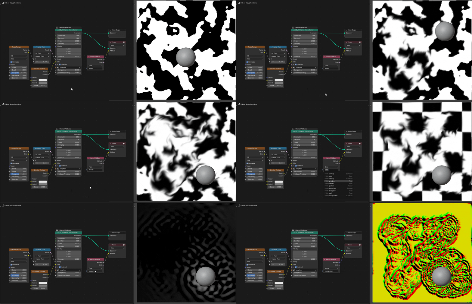
Description
A 2D fluid solver operating on a grid, advecting velocity, pressure, density, and color fields with configurable damping and external force/collision input, for smoke and liquid style simulations.
Inputs
- NameTypeDescription
- Resolution
IntegerNumber of vertices in the X direction - Iterations
IntegerNumber of pressure solve iterations per-frame. Higher values produce more realistic results. - Scale
FloatScale of the simulation grid - Damping
FloatAmount the velocity is damped each step - Velocity
VectorVelocity field of the fluid - Pressure
FloatPressure field of the fluid - Density
FloatDensity field of the fluid - Color
ColorColor field carried along by the fluid - External
BooleanEnable interaction with an external object - External Object
ObjectObject that interacts with the fluid - External Dampening
FloatHow much to damp the velocity - External Collision Proximity
FloatDistance within which the external object affects the fluid
Outputs
- NameTypeDescription
- Geometry
GeometryGrid geometry with the updated simulation fields
A3D_Age Cull
Description
Deletes Geometry on the selected Domain when age is greater than or equal to max_age. Used with other Age* nodes.
Inputs
- NameTypeDescription
- Geometry
GeometryGeometry to remove expired elements from - Selection
BooleanElements that can be culled - Domain
MenuDomain to cull on
Outputs
- NameTypeDescription
- Geometry
GeometryGeometry with expired elements removed
A3D_Age Initialize
Description
Write the attribute max_age on the selected Domain. Used with other Age* nodes.
Inputs
- NameTypeDescription
- Geometry
GeometryGeometry to store the max_age attribute on - Selection
BooleanElements to initialize - Domain
MenuDomain to store max_age on - Max Age
FloatAge at which an element is considered expired
Outputs
- NameTypeDescription
- Geometry
GeometryGeometry with the max_age attribute stored
A3D_Age Update
Description
Increments the attribute age by input Delta Time on the selected Domain. Used with other Age* nodes.
Inputs
- NameTypeDescription
- Geometry
GeometryGeometry to update the age attribute on - Selection
BooleanElements to age - Delta Time
FloatAmount of time added to age - Domain
MenuDomain the age attribute is stored on
Outputs
- NameTypeDescription
- Geometry
GeometryGeometry with the age attribute updated
A3D_Derive Velocity
Description
Derives a per-point velocity vector from the difference between a previous and current position, with damping applied.
Inputs
- NameTypeDescription
- Previous Position
VectorPosition on the previous step - Position
VectorCurrent position - Damping
FloatDamping applied to the velocity
Outputs
- NameTypeDescription
- Vector
VectorDerived velocity
A3D_Geometry Motion Path
Description
Builds a trailing motion-path mesh from a set of animated points, with configurable substeps and a maximum trail age.
Inputs
- NameTypeDescription
- Points
GeometryAnimated points to trace - Selection
BooleanPoints to include - Substeps
IntegerQuality of inbetween motion estimation - Max Trail Age
FloatMaximum age of the trail before it is removed
Outputs
- NameTypeDescription
- Geometry
GeometryGenerated motion path geometry
A3D_Ground Impact Solve
Description
Analytically solves for where and when a ballistic trajectory (defined by an initial position, velocity, and gravity) intersects a plane, returning the impact time, position, and velocity.
Inputs
- NameTypeDescription
- Initial Position
VectorPosition at launch - Initial Velocity
VectorVelocity at launch - Gravity
VectorGravity acceleration vector - Plane Point
VectorPoint on the plane - Plane Normal
VectorNormal of the plane
Outputs
- NameTypeDescription
- Impact Time
FloatTime until the trajectory reaches the plane - Impact Position
VectorPosition where the trajectory reaches the plane - Impact Velocity
VectorVelocity at the moment of impact
A3D_IK Solver
Description
Solves inverse kinematics for a chain of geometry between a start and end point (with an optional pole target), iterating to convergence.
Inputs
- NameTypeDescription
- Geometry
GeometryChain to solve - Iterations
IntegerNumber of solver iterations - Start
VectorPosition of the chain root - End
VectorTarget position for the end of the chain - Pole
VectorPole target controlling the bend direction
Outputs
- NameTypeDescription
- Geometry
GeometrySolved chain
A3D_Object Motion Path
Description
Builds a trailing motion-path mesh tracking an object's movement over time, with configurable substeps and maximum trail age.
Inputs
- NameTypeDescription
- Object
ObjectObject to trace - Substeps
IntegerQuality of inbetween motion estimation - Max Trail Age
FloatMaximum age of the trail before it is removed
Outputs
- NameTypeDescription
- Geometry
GeometryGenerated motion path geometry
A3D_Particle Tracking
Description
Emits and tracks particles toward a target position with per-particle emission/tracking delay and velocity ranges plus noise-driven trajectory variation, outputting velocity and age attributes.
Inputs
- NameTypeDescription
- Geometry
GeometryGeometry to emit particles from - Selection
BooleanPoints that emit particles - Target Position
Vector(Required) world space point particles tend to follow - Emission Delay Min
FloatMinimum time to wait before emitting a particle - Emission Delay Max
FloatMaximum time to wait before emitting a particle - Emission Velocity
FloatInitial velocity during the launch phase, before Tracking Delay has elapsed - Tracking Delay
FloatTime to wait before the particle begins to seek Target Position - Tracking Velocity
FloatVelocity during the tracking phase, after Tracking Delay has elapsed - Trajectory Noise Scale
FloatScale of noise that alters trajectory - Trajectory Noise Strength
FloatStrength of noise that alters trajectory
Outputs
- NameTypeDescription
- Geometry
GeometryEmitted particles - Velocity
VectorVelocity of each particle - Age
FloatCurrent age of each particle - Start Age
FloatAge at which each particle starts
A3D_Pressure Correction
Description
Computes the position correction vector for a point that applies an internal pressure force to the geometry, scaled by a pressure coefficient and the simulation time step.
Inputs
- NameTypeDescription
- Geometry
GeometryGeometry the pressure is applied to - Delta Time
FloatTime step of the simulation - Pressure Coefficient
FloatStrength of the pressure force
Outputs
- NameTypeDescription
- Vector
VectorPosition correction for the point
A3D_Solve XPBD Edge Constraints
Description
Solves extended position-based dynamics (XPBD) edge/distance constraints for a given stiffness and tension over a maximum iteration count, returning the accumulated position correction.
Inputs
- NameTypeDescription
- Max Iterations
IntegerMaximum number of solver iterations - Stiffness
FloatStiffness of the edge constraints - Tension
FloatTension in the edges
Outputs
- NameTypeDescription
- Accumulated Correction
VectorSum of the correction vectors for the point
A3D_Sphere Collision
Description
Tests two indexed spheres for collision, returning whether they collided, their overlap amount, and the collision normal.
Inputs
- NameTypeDescription
- Index A
IntegerIndex of the first sphere - Index B
IntegerIndex of the second sphere
Outputs
- NameTypeDescription
- Collided
BooleanTrue if the spheres collide - Overlap
FloatAmount the spheres overlap - Normal
VectorCollision normal
A3D_Velocity Simulation
Description
Derives and writes a per-point velocity attribute across simulation steps, with damping.
Inputs
- NameTypeDescription
- Geometry
GeometryGeometry to simulate velocity on - Damping
FloatHow much to damp the velocity - Write Attribute
BooleanStore Named Attribute containing Velocity value - Velocity Attribute
StringName of the attribute to store
Outputs
- NameTypeDescription
- Geometry
GeometryGeometry with the updated velocity - Velocity
VectorSimulated velocity of each element
A3D_XPBD Solver
Description
A full extended position-based dynamics (XPBD) cloth/soft-body solver. Supports fixed points, external force, damping, stretch stiffness, pretension, pressure, friction, and mesh collision, with pre/post-solve closures for custom constraint injection.
Inputs
- NameTypeDescription
- Geometry
GeometryGeometry to simulate - Substeps
IntegerQuality of simulation - Fixed Points
BooleanWhich points are fixed/immobile - Animated
BooleanAre fixed points animated/updating every frame (use for rigs) - External Force
VectorExternal force acting on simulation - Damping
FloatVelocity reduction (recommended >0) - Stretch Stiffness
FloatHow much the rope resists stretching. High values require higher steps - Pretension
FloatTension in the rope before simulation. Helps keep ropes stiff - Pre Solve Closure
ClosureClosure run before each solve step - Post Solve Closure
ClosureClosure run after each solve step - Pressure
BooleanEnable pressure forces - Pressure Coefficient
FloatStrength of the pressure force - Friction
BooleanEnable friction - Friction Coefficient
FloatStrength of the friction - Collision
BooleanEnable collision - Collision Substeps
IntegerNumber of substeps used for collision - Collision Use Object
BooleanCollide with an object instead of a mesh - Collision Object
ObjectObject to collide with - Collision Mesh
GeometryMesh to collide with
Outputs
- NameTypeDescription
- Geometry
GeometrySimulated Geometry
A3D_XPBD Solver Repeat
Description
Runs a position-based dynamics (PBD) solve over multiple outer iterations and substeps, with fixed points, external force, damping, stretch stiffness, pretension, volume preservation, and mesh collision.
Inputs
- NameTypeDescription
- Geometry
GeometryRope geometry to simulate - Iterations
IntegerNumber of constraint solver iterations - Substeps
IntegerQuality of simulation - Fixed Points
BooleanWhich points are fixed/immobile - Animated
BooleanAre fixed points animated/updating every frame (use for rigs) - External Force
VectorExternal force acting on simulation - Damping
FloatVelocity reduction (recommended >0) - Stretch Stiffness
FloatHow much the rope resists stretching. High values require higher steps - Pretension
FloatTension in the rope before simulation. Helps keep ropes stiff - Pressure
BooleanKeep the rope from losing volume when stretched - Pressure Coefficient
FloatStrength of the pressure force - Collision
BooleanEnable collision with a mesh - Collision Substeps
IntegerNumber of substeps used for collision - Collision Mesh
GeometryMesh the rope collides with
Outputs
- NameTypeDescription
- Geometry
GeometrySimulated rope geometry
A3D_XPBD Solver Step
Description
A single time-stepped iteration of the XPBD solver, taking an explicit delta time and previous position and exposing the same stiffness/pressure/friction/collision controls as the full solver.
Inputs
- NameTypeDescription
- Delta Time
FloatTime step of the simulation - Geometry
GeometryRope geometry to simulate - Previous Position
VectorPositions from the previous step - Substeps
IntegerNumber of substeps - Fixed
BooleanWhich points are fixed in place - External Force
VectorExternal force acting on the simulation - Damping
FloatVelocity reduction applied each step - Stiffness
FloatHow much the rope resists stretching - Pretension
FloatTension in the rope before simulation - Pressure
BooleanEnable pressure forces - Pressure Coefficient
FloatStrength of the pressure force - Friction
BooleanEnable friction - Friction Coefficient
FloatStrength of the friction - Collision
BooleanEnable collision - Collision Substeps
IntegerNumber of substeps used for collision - Collision Mesh
GeometryMesh to collide with
Outputs
- NameTypeDescription
- Geometry
GeometrySimulated rope geometry - Position
VectorUpdated positions
Debugging & Visualization
A3D_Debug Vectors
Description
Generates arrow-like geometry that visualizes vectors, for debugging vector data.
Inputs
- NameTypeDescription
- Geometry
GeometryPoints to draw the vectors at - Vertices
IntegerThe number of vertices on the top and bottom circles - Vector
VectorVector to visualize - Length
FloatLength of the arrows - Radius
FloatRadius of the arrows
Outputs
- NameTypeDescription
- Geometry
GeometryGenerated debug arrow geometry
Cameras & Transforms
A3D_Active Camera Transform
Description
Returns the transform (and separately, location/rotation/scale) of the scene's active camera, with a mode switch for which representation to output.
Inputs
- NameTypeDescription
- Mode
MenuWhich representation of the transform to output
Outputs
- NameTypeDescription
- Transform
MatrixTransformation matrix containing the location, rotation and scale of the camera - Location
VectorLocation of the active camera - Rotation
RotationRotation of the active camera - Scale
VectorScale of the active camera
A3D_Camera Cull
Description
Removes or masks geometry that falls outside a camera's view frustum, with padding and a minimum-distance cutoff, useful for render-time optimization.
Inputs
- NameTypeDescription
- Geometry
GeometryGeometry to cull - Source
MenuWhere the camera comes from - Camera
ObjectCamera object to cull against - Domain
MenuWhich type of element to Cull - Padding
FloatExtend bounds of frustum beyond edge of screen - Min Distance
FloatMinimum distance after which to begin culling
Outputs
- NameTypeDescription
- Geometry
GeometryGeometry with out-of-view elements removed
A3D_Camera FOV
Description
Returns the horizontal and vertical field of view of a camera, optionally defaulting to the active scene camera.
Inputs
- NameTypeDescription
- Use Active
BooleanUse the active scene camera - Camera
ObjectCamera object to read the field of view from
Outputs
- NameTypeDescription
- Horizontal FOV
FloatHorizontal field of view of the camera - Vertical FOV
FloatVertical field of view of the camera
A3D_Extended Camera Info
Description
A comprehensive camera data node. combines transform, projection matrix, focal length, sensor size, shift, clipping planes, focus distance, orthographic state/scale, and both view distance/direction and field-of-view in one lookup.
Inputs
- NameTypeDescription
- Source
MenuWhere the camera comes from - Camera
ObjectCamera object to read
Outputs
- NameTypeDescription
- Transform
MatrixTransformation matrix containing the location, rotation and scale of the camera - Location
VectorLocation of the camera - Rotation
RotationRotation of the camera - Scale
VectorScale of the camera - Projection Matrix
MatrixCamera projection matrix - Focal Length
FloatPerspective camera focal length - Sensor
VectorSize of the camera sensor - Shift
VectorCamera shift - Clip Start
FloatCamera near clipping distance - Clip End
FloatCamera far clipping distance - Focus Distance
FloatDistance to the focus point for depth of field - Is Orthographic
BooleanWhether the camera is using orthographic projection - Orthographic Scale
FloatOrthographic camera scale (similar to zoom) - Distance
FloatDistance from the camera to the evaluated position - Direction
VectorDirection from the camera to the evaluated position - Horizontal FOV
FloatHorizontal field of view of the camera - Vertical FOV
FloatVertical field of view of the camera
A3D_Self Transform
Description
Applies the self object's transform matrix to the input geometry, with optional inversion.
Inputs
- NameTypeDescription
- Geometry
GeometryGeometry to transform - Invert
BooleanApply the inverse of the transform instead
Outputs
- NameTypeDescription
- Geometry
GeometryTransformed geometry
A3D_View Transform
Description
Transforms a world-space position through a camera's view into view-space, clip-space (with W), and NDC coordinates.
Inputs
- NameTypeDescription
- Source
MenuWhere the camera comes from - Camera
ObjectCamera object to transform through - Position
VectorPosition to transform
Outputs
- NameTypeDescription
- View Space Position
VectorPosition transformed to view space - Clip Space Position
VectorPosition transformed to clip space - Clip Space W
FloatDepth of transformed point in clip space - NDC Position
VectorPosition transformed to normalized device coordinates